Negotiable
The date of payment from buyers deliver within days
Hebei
Long-term effective
2017-08-27 04:19
167
 Company Profile

By certification [File Integrity]
Contact:Ms. Tiffany Tang(Mr.)
Email:
Telephone:
Phone:
Area:Hebei
Address:Hebei
Website: http://cztslzq.artstx.com/
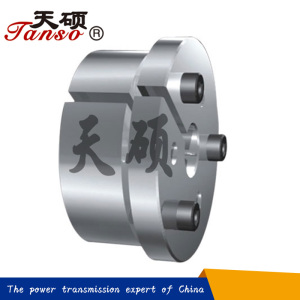
Tanso Shaft Locking Devices connect hubs solidly to shafts, using a keyless mechanical interference fit, to transmit torque or to withstand axial thrust. This mechanical interference fit utilizes screw tension in the Shaft Locking Device, converted into radial pressure via an inclined plane. This pressure expands the Shaft Locking Device to eliminate the gap between the hub and the shaft. The Shaft Locking Device uses the friction bond between the Shaft Locking Device and the shaft/hub to create a zero backlash connection. This connection is easily releasable to remove the mechanical interference fit.
Tanso Shaft Locking Devices expand to fill the gap between the shaft and hub, allowing for easy installation and removal, saving time over traditional interference fit techniques. The contact pressures created using a Shaft Locking Device can be greater than traditional interference fit pressures, allowing for more torque to be transmitted or shorter hubs to be used. The easy installation also allows the hub to be positioned more accurately on the shaft, and can facilitate angular timing of the hub.
Easy assembly and disassembly
Both actions take place by locking and unlocking the clamping screws with common tools.
The use of a torque wrench is only necessary when a more precise torque is required.
Superior holding power
The action of the clamping cones creates shaft clamping torque superior to a normal keyed hub.
Overload protection
When the pre-set torque is exceeded locking device will slip, preventing the connected elements from being broken.
Note: Locking units are not friction couplings, so excessive slip will cause damage.
Easy adjustment
Combining the locking device design of smooth cone action with superior holding power, the hub can be clamped at any position along a shaft, eliminating the need for lock washers, spacers , stop rings, etc.
Specific product description
Locking assembly with single taper design.It is suitable for high torques.Provide good concentricity and self centering.A small axial movement of hub during the installation operation may occur.
Features:
1.High torque; internal shaft locking device
2.Exceptional concentricity
3.Self-centering
4.Axial hub position fixed during clamping

| Dimensions | Rating load | Hexagon bolt | Pressure between lock and shaft |
Pressure between lock and hub |
Mass | |||||||||
| pr | pr | kg | ||||||||||||
| d | D | L4 | L3 | L2 | D1 | L1 | Axial force |
Torque | d1 | n | MA | N/mm2 | N/mm2 | |
| Ft | Mt | (N*m) | ||||||||||||
| KN | KN m | |||||||||||||
| 14 | 55 | 17 | 30 | 22 | 62 | 38 | 18 | 127 | M8 | 3 | 25 | 208 | 52.5 | 0.48 |
| 16 | 55 | 17 | 30 | 22 | 62 | 38 | 18 | 142 | M8 | 3 | 25 | 181 | 52.5 | 0.47 |
| 18 | 55 | 17 | 30 | 22 | 62 | 38 | 18 | 157 | M8 | 3 | 25 | 161 | 52.5 | 0.46 |
| 19 | 55 | 17 | 30 | 22 | 62 | 38 | 18 | 165 | M8 | 3 | 25 | 152 | 52.5 | 0.46 |
| 20 | 55 | 17 | 30 | 22 | 62 | 38 | 18 | 172 | M8 | 3 | 25 | 145 | 52.5 | 0.45 |
| 22 | 55 | 17 | 30 | 22 | 62 | 38 | 25.5 | 285 | M8 | 3 | 35 | 186 | 75 | 0.44 |
| 24 | 55 | 17 | 30 | 22 | 62 | 38 | 25.5 | 307 | M8 | 3 | 35 | 170 | 75 | 0.42 |
| 25 | 55 | 17 | 30 | 22 | 62 | 38 | 25.5 | 315 | M8 | 3 | 35 | 163 | 75 | 0.41 |
| 28 | 55 | 17 | 30 | 22 | 62 | 38 | 31.5 | 435 | M8 | 3 | 41 | 175 | 89 | 0.39 |
| 30 | 55 | 17 | 30 | 22 | 62 | 38 | 31.5 | 472 | M8 | 3 | 41 | 163 | 89 | 0.37 |
| 24 | 65 | 17 | 30 | 22 | 72 | 38 | 37.4 | 440 | M8 | 5 | 30 | 244 | 90 | 0.62 |
| 25 | 65 | 17 | 30 | 22 | 72 | 38 | 37.4 | 460 | M8 | 5 | 30 | 234 | 90 | 0.61 |
| 28 | 65 | 17 | 30 | 22 | 72 | 38 | 43.6 | 600 | M8 | 5 | 35 | 243 | 105 | 0.58 |
| 30 | 65 | 17 | 30 | 22 | 72 | 38 | 43.6 | 640 | M8 | 5 | 35 | 227 | 105 | 0.56 |
| 32 | 65 | 17 | 30 | 22 | 72 | 38 | 43.6 | 690 | M8 | 5 | 35 | 213 | 105 | 0.55 |
| 35 | 65 | 17 | 30 | 22 | 72 | 38 | 52.5 | 910 | M8 | 5 | 41 | 234 | 126 | 0.51 |
| 38 | 65 | 17 | 30 | 22 | 72 | 38 | 52.5 | 990 | M8 | 5 | 41 | 216 | 126 | 0.48 |
| 40 | 65 | 17 | 30 | 22 | 72 | 38 | 52.5 | 1050 | M8 | 5 | 41 | 205 | 125 | 0.46 |
| 30 | 80 | 20 | 33 | 25 | 87 | 41 | 52.4 | 780 | M8 | 7 | 30 | 232 | 87 | 1.01 |
| 32 | 80 | 20 | 33 | 25 | 87 | 41 | 52.4 | 830 | M8 | 7 | 30 | 217.5 | 87 | 0.99 |
| 35 | 80 | 20 | 33 | 25 | 87 | 41 | 61 | 1060 | M8 | 7 | 35 | 232 | 102 | 0.96 |
| 38 | 80 | 20 | 33 | 25 | 87 | 41 | 61 | 1150 | M8 | 7 | 35 | 214 | 102 | 0.92 |
| 40 | 80 | 20 | 33 | 25 | 87 | 41 | 61 | 1220 | M8 | 7 | 35 | 203 | 102 | 0.89 |
| 42 | 80 | 20 | 33 | 25 | 87 | 41 | 73.5 | 1540 | M8 | 7 | 41 | 233 | 122 | 0.86 |
| 45 | 80 | 20 | 33 | 25 | 87 | 41 | 73.5 | 1650 | M8 | 7 | 41 | 217 | 122 | 0.82 |
| 48 | 80 | 20 | 33 | 25 | 87 | 41 | 73.5 | 1760 | M8 | 7 | 41 | 203 | 122 | 0.76 |
| 50 | 80 | 20 | 33 | 25 | 87 | 41 | 73.5 | 1830 | M8 | 7 | 41 | 195 | 122 | 0.73 |